
The low frequency version (channel 2 to 6 - 55 MHz to 90 MHz) of this kit has 4 poles. Each pole has approximately 11 to 14 dB of attenuation at the resonant frequency. The high frequency version channels 14 to 22 and channels 7 to 13 (100 MHz to 215 MHz) has 3 poles, each pole has approximately 13 to 18 dB of attenuation at the resonant frequency, The band width (notch width) is approximately 300 to 500 KHz for each pole of either filter design. Since each pole may be adjusted independently the notch depth and width are somewhat variable and adjustable. If all poles of the filter are set to the same resonant frequency the overall depth will be 45 to 55 dB and the notch width will be approximately 0.5 MHz. However, if you set each pole of your filter to a different frequency the overall depth will be approximately 15 dB and the notch width will be 1.0 to 1.5 MHz.
If you want to `trap-out' an unwanted carrier it is normal to adjust all poles to the same frequency. You could `trap-out' a carrier which has been placed within a TV channel between the color-burst signal and the audio carrier, without any appreciable affect On either of the desired signals. This carrier that you might want to remove normally causes a annoying beeping sound, and causes the picture to be unwatchable. By removing only the unwanted carrier, you can restore a good picture.
If you want to remove an unwanted channel you would need to use 2 of these filters. One filter would be adjusted to remove the video information and you would use the other filter to remove the audio and color information. Most of the video information is contained within a 600 KHz bandwidth, therefore one filter will provide approximately 40 dB of attenuation with a notch width of about 600 KHz. Typically you will adjust 3 poles of a 4 pole filter or 2 poles of a 3 pole filter for a frequency about 100 KHz above the video frequency of the desired channel and the remaining pole would be adjusted to a frequency approximately 400 KHz higher than the video frequency. (see chart of frequencies for channels 2 to 22).
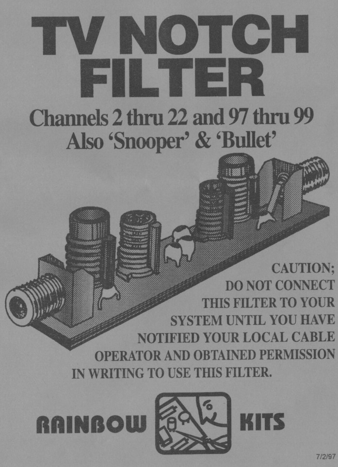
The "BULLET" is a signal used to turn on and off cable services. The signal is used in some systems to remotely activate / deactivate the premium services supplied by the operator without, actually having to go to each location.
There is a signal inserted in the cable on some systems that is used to detect cable leaks and unauthorized equipment, to detect this signal you use a device called a snooper.
The 'Bullet and Snooper' are best aligned with a sweep generator or spectrum analyzer. You must know the exact frequency that is used on your system, and the filter must be calibrated to that frequency.


To purchase this kit, please visit www.rainbowkits.com. NOTE: This site is NOT affiliated in any way with Rainbow Kits. This information is provided here exclusively for its informational value to the visitors of the Dewtronics Website as per this site's policy.